







RO Membrane Selection for Seawater Desalination
RO Membrane Selection for Seawater Desalination
Membrane selection decides most of a seawater reverse osmosis plant's lifetime behaviour: how much pressure the high-pressure pump must deliver, how fast rejection degrades, how often elements need cleaning, and how much spare capacity the array must carry. A plant specified around the wrong element family will run — it simply runs at higher specific energy and with a shorter replacement cycle. This guide walks through the decisions that matter, in the order a project team usually faces them.
🌊 Why Membrane Choice Sets the Whole Plant's Performance
Seawater at 35,000 mg/L total dissolved solids exerts an osmotic pressure of roughly 2.4 to 2.8 MPa. To produce permeate at a useful flux, the feed side must be pressurised well above that value, and every 0.1 MPa of extra feed pressure costs energy every hour of the plant's life. Element selection therefore translates directly into operating cost: a membrane with higher stabilised rejection lets the designer run a lower net driving pressure for the same product quality.
Two numbers describe most of this behaviour. Stabilised salt rejection of 99.6% to 99.8% is the normal band for premium seawater elements, while standard brackish elements sit at 99.0% to 99.5%. Design flux for seawater service is typically held to 12 to 18 L/m²h, roughly half the flux allowed in brackish duty, because higher flux accelerates colloidal and organic fouling on a high-salinity feed.
🧪 The Three Element Families in a Seawater Plant
Most seawater plants use one of three families, and the choice is usually made on feed salinity and energy price rather than on catalogue preference.
Standard seawater elements are built for feeds above 30,000 mg/L and rated to 800 psi (5.5 MPa) or, in high-pressure variants, 1,000 psi (6.9 MPa). They deliver the highest rejection and are the default for open-intake coastal plants.
Low-energy seawater elements trade a small amount of rejection for permeability, reducing feed pressure by roughly 10% to 15% at the cost of slightly higher permeate conductivity. Where energy is expensive and a second-pass polish is available, this is often the better economic choice.
Brackish or high-rejection brackish elements appear in the second pass or in low-salinity wells and estuaries, where feed TDS may be under 10,000 mg/L. They are rated to 200 to 400 psi and must never be substituted into a true seawater first pass — the pressure envelope alone rules it out.
📊 Five Datasheet Numbers That Actually Matter
Datasheets run to several pages. In practice, five values drive the hydraulic design, and they should be compared on the same test conditions — usually 32,000 mg/L NaCl, 25 °C, 10% recovery and a stated pH.
- Stabilised salt rejection — the figure after conditioning, not the initial spot value. Ask for the minimum, not the average.
- Active membrane area — 37.2 m² (400 ft²) and 41 m² (440 ft²) are the two common seawater formats; area sets how many elements a target flow needs.
- Design flux — the manufacturer's recommended maximum for seawater service, not the burst limit.
- Maximum feed pressure and pressure drop — the array's pressure envelope and the per-element limit that keeps the last element from star back-pressure.
- Feed spacer thickness — 28 to 34 mil for seawater duty. Thicker spacers lower pressure drop and foul more slowly, at the cost of a few percent of packing density.
🔧 One-Stage or Two-Stage Configuration?
A single-stage seawater array recovers 35% to 45% of the feed, limited by the osmotic pressure of the concentrate leaving the last element. Where the site needs higher recovery, a two-stage or partial two-pass arrangement pushes overall recovery to 50% to 55%, but the second stage sees warmer, more concentrated feed and must be sized on that basis.
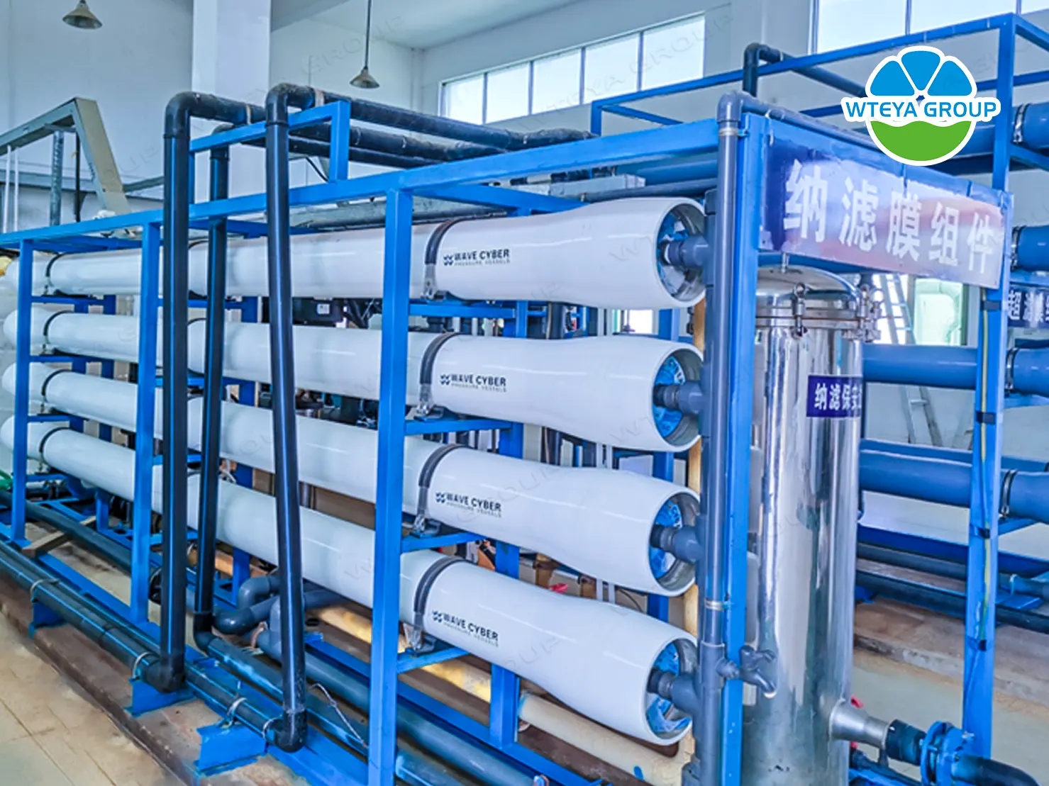
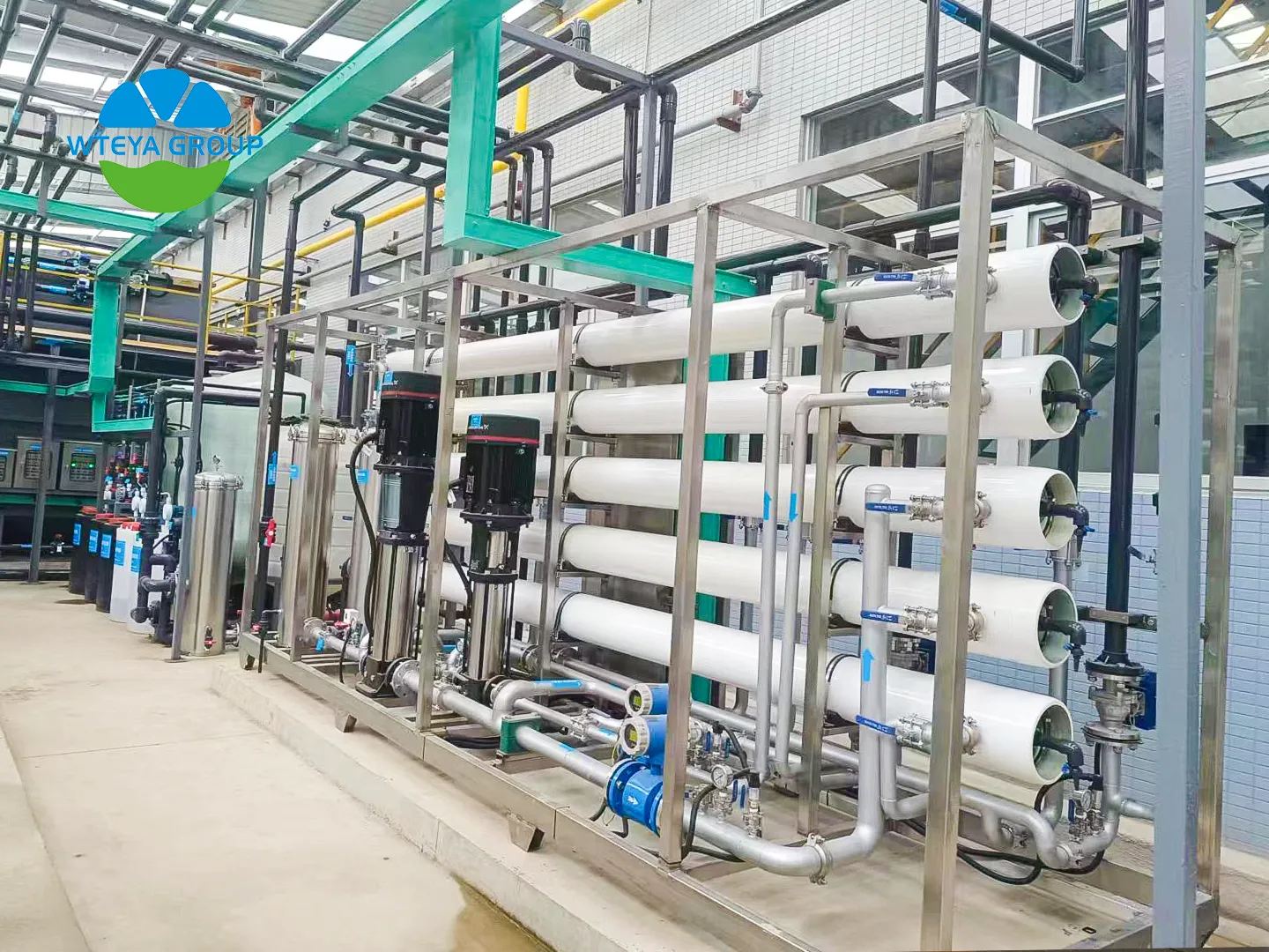
Vessel arrays are usually written as a ratio — 6:4, 5:3, 8:4 — meaning vessels in the first stage to vessels in the second. The ratio should be set so that the average flux in the first stage stays within the design band and the last element's concentrate flow stays above the manufacturer's minimum, typically 8 to 10 m³/h per vessel. Undersized concentrate flow is one of the most common causes of premature scaling.
🧱 Construction Details That Decide Service Life
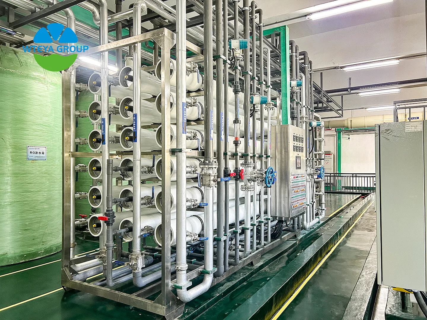
Almost all seawater elements are thin-film composite polyamide on a polysulfone support, wrapped in fiberglass with an anti-telescoping device at each end. Differences that matter in service are the quality of the polyamide layer, the brine seal design, and whether the element is rated for the cleaning regime the plant intends to use.
Check the stated pH range for continuous operation, commonly 2 to 11, and the short-term cleaning range, which is usually wider. If the plant will run alkaline cleaning at pH 11 to 12 for organic fouling, confirm the element is rated for it — the wrap and the glue line, not the membrane chemistry, are usually the limiting item.
♻️ Fouling, Cleaning and Replacement Planning
Elements should be cleaned on normalised performance, not on a calendar. The usual triggers are a 10% to 15% drop in normalised permeate flow, a 5% to 10% rise in normalised salt passage, or a rise in differential pressure across the array of 15% or more against the commissioning baseline. Cleaning earlier than that wastes chemical and labour; cleaning much later usually means the fouling has become irreversible.
Plan replacement rather than react to failure. Seawater elements commonly last 3 to 5 years with adequate pretreatment, longer where coagulation and media filtration are well controlled. Carrying 10% to 15% spare elements on site lets the operator swap a failed element without derating the plant, which matters in remote or island installations where delivery takes weeks.
🏆 Why Choose WTEYA
WTEYA builds seawater and brackish water RO systems as complete packages — intake and pretreatment, membrane arrays, energy recovery, controls and commissioning — so membrane selection is matched to the actual feed analysis rather than to a stock catalogue. Systems are assembled in our own factory, tested before shipment, and supported with a documented operating envelope for cleaning and replacement.
For partners reselling or installing desalination equipment, we supply containerised and skid-mounted plants with full documentation, spare parts lists and factory training. Become a WTEYA authorized dealer to access exclusive territories, competitive factory pricing and full technical support.
❓ Frequently Asked Questions
How long do seawater RO membranes last?
Typically 3 to 5 years. Life is set mainly by pretreatment quality and cleaning discipline; plants that clean on normalised flow decline rather than on a fixed schedule routinely reach the upper end.
Can I use brackish water membranes for seawater?
No. Brackish elements are rated to roughly 200 to 400 psi and cannot withstand the 5.5 MPa or more needed to overcome seawater osmotic pressure; the element will fail mechanically even if rejection looks acceptable on paper.
How many spare elements should a plant keep?
Carry 10% to 15% of the array count. That is enough to replace a failed element immediately without derating production, and it avoids waiting weeks for delivery on island or remote sites.
Send us your feed water analysis and target capacity, and our engineers will return an element count, array configuration and expected specific energy for your project.
📲 WhatsApp: +86-1802 5185 143
📧 Email: sales@wteya.com
🌐 Website: www.wteyaa.com

Previous: Desalination and the Environment: Impacts and Mitigation
Next: No More